
Steel‑plate cutting is a fundamental procedure for metal fabrication, infrastructure construction, equipment manufacturing and home repairs. Improper selection of cutting methods may result in rough cut edges, plate deformation, material waste, and even safety hazards such as fire and arc‑flash burns. This article systematically covers six mainstream cutting approaches: oxy‑fuel flame cutting, plasma cutting, laser cutting, waterjet cutting, angle‑grinder cutting, and shearing.
1. Basic Knowledge of Steel‑Plate Cutting
1.1 Distinction Between Steel Plates and Thin Sheets
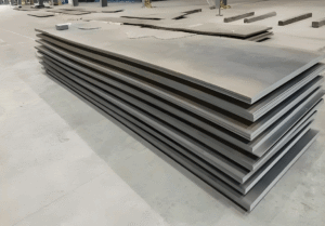
In industrial practice, 6 mm serves as the general dividing line: material with thickness ≥ 6 mm is defined as steel plate, while material thinner than 6 mm is steel sheet. Thickness is the core factor for selecting cutting technology. Picking an unsuitable process will greatly reduce efficiency and raise costs.
1.2 Common Steel‑Plate Materials and Cutting Characteristics
Differences in physical and chemical properties directly determine feasible cutting processes:
- Mild steel (Q235 / A36): Compatible with nearly all cutting methods. It is the most widely‑used structural steel.
- Stainless steel: Chromium forms a dense oxide film that inhibits combustion reactions. Oxy‑fuel flame cutting is not applicable; plasma, laser or waterjet cutting are preferred.
- Alloy steel / high‑strength wear‑resistant steel: Heat input may alter mechanical properties near cut edges. Cold‑cutting processes are recommended to control the heat‑affected zone (HAZ).
- Galvanized steel plate: Zinc vaporizes and generates toxic fumes during thermal cutting. Adequate ventilation and respiratory protection are mandatory.
1.3 Core Evaluation Metrics for Cutting Quality
Cutting quality is assessed across five key dimensions to match processes to project requirements:
- Cut‑edge squareness: Perpendicular deviation between the cut surface and plate surface, measured in mm or degrees. Laser cutting delivers the best squareness; oxy‑fuel flame cutting produces the largest deviation.
- Heat‑affected zone (HAZ) width: The region where material properties change under high‑temperature exposure. Waterjet cutting creates no HAZ; oxy‑fuel flame cutting yields the widest HAZ.
- Burr / dross buildup: Solidified molten‑metal protrusions along cut edges. Laser and fine‑plasma cuts produce almost no dross; oxy‑fuel and conventional plasma generate substantial dross.
- Dimensional tolerance: Deviation between actual machined dimensions and design values. Laser cutting achieves tolerances within ±0.1 mm; oxy‑fuel flame cutting typically ranges ±1.5‑2.5 mm.
- Surface roughness: Flatness of the cut surface, quantified by Ra values; lower Ra indicates smoother edges.
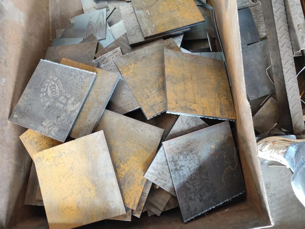
2. Six Mainstream Steel‑Plate Cutting Methods
2.1 Oxy‑Fuel Flame Cutting
Oxy‑fuel flame cutting is a traditional thermal‑cutting process and the primary solution for thick‑plate machining. It uses fuel gas such as acetylene or propane to heat steel to its ignition point (~1350 °C). High‑pressure pure oxygen triggers vigorous oxidative combustion, while high‑velocity oxygen flow blows away molten slag to form a continuous cut.
Key Parameters
- Applicable thickness: 6 mm‑300 mm; optimal for medium‑to‑heavy plates above 20 mm
- Kerf width: 2‑6 mm
- Dimensional tolerance: ±1.5‑±2.5 mm
- HAZ width: 3‑5 mm
Core Advantages: Low equipment investment, high portability, no external power supply required, capable of cutting extra‑thick plates; single torch supports on‑site operations.
Main Limitations: Only works for ferrous carbon steels; broad HAZ may alter material properties; low cutting accuracy, slow cutting speed; thin plates are prone to edge burn‑off and deformation.
Typical Applications: Heavy steel‑structure fabrication, shipbuilding, outdoor field construction, rough machining of thick plates, demolition work.
2.2 Plasma Cutting
Plasma cutting employs high‑temperature ionized plasma arcs (above 15 000 °C) to melt metal, and high‑speed gas jets expel molten slag to separate workpieces. Independent of metal oxidation reactions, it cuts all electrically conductive metals and represents a mainstream process for small‑and‑medium‑scale fabrication.
Key Parameters
- Applicable thickness: 0.5 mm‑50 mm (consumer‑grade units generally ≤25 mm; heavy‑duty industrial models reach 150 mm)
- Kerf width: 1‑3 mm
- Dimensional tolerance: ±0.3‑±1.5 mm (fine plasma achieves ±0.1 mm)
- HAZ width: 1‑3 mm
Core Advantages: Cutting speed is 3‑5 times faster than oxy‑fuel flame cutting; processes all conductive metals including stainless steel, aluminum and copper; relatively clean cut edges, high cost‑performance for medium‑and‑thin plates.
Main Limitations: Natural bevel taper occurs on thick‑plate cuts; requires power supply and compressed‑air supply; moderate equipment cost, fast consumption of wearing parts.
Typical Applications: Small‑and‑medium sheet‑metal fabrication, stainless‑steel and non‑ferrous‑metal cutting, workshops and maintenance jobs, profiling of irregular parts.
2.3 Laser Cutting
Laser cutting uses a focused high‑power laser beam to locally melt or vaporize metal. Assist gases such as oxygen or nitrogen blow away molten slag. It delivers the highest precision for thin‑plate processing.
Key Parameters
- Applicable thickness: 0.1 mm‑25 mm; optimal for sheets below 10 mm
- Kerf width: 0.1‑0.3 mm
- Dimensional tolerance: ±0.1‑±0.5 mm
- HAZ width: ≤0.5 mm
Core Advantages: Industry‑leading precision, capable of highly complex contours; nearly burr‑free edges requiring minimal secondary grinding; minimal thermal distortion; high CNC automation for high‑volume production.
Main Limitations: High equipment purchase and maintenance costs; efficiency drops sharply for thick plates with poor economy; high requirements for plate flatness.
Typical Applications: Precision mechanical‑part manufacturing, electronic hardware components, mass‑production orders, complex‑profile cutting, high‑end sheet‑metal fabrication.
2.4 Abrasive Waterjet Cutting
Waterjet cutting is a cold‑cutting technology. A high‑pressure pump pressurizes water to hundreds of megapascals. Mixed with garnet abrasive, the jet ejects through a fine nozzle, eroding material by high‑velocity abrasive impact.
Key Parameters
- Applicable thickness: 1 mm‑300 mm, suitable for full thickness ranges
- Kerf width: 0.8‑1.5 mm
- Dimensional tolerance: ±0.1 mm
- HAZ: None
Core Advantages: Zero heat input, mechanical properties of base material remain unchanged; cuts nearly all materials: metals, stone, glass, composites; clean, vertically‑aligned cut edges; no toxic fumes or dust, environmentally friendly.
Main Limitations: Slow cutting speed, far less efficient than thermal cutting; high operating costs from continuous abrasive consumption; large footprint and high initial investment.
Typical Applications: Heat‑sensitive‑material processing, precision parts of high‑strength steel and titanium alloys, prototype development, multi‑layer composite materials, components requiring zero thermal deformation.
2.5 Angle‑Grinder Cutting
Angle‑grinder cutting relies on high‑speed rotating resin‑reinforced cutting discs to separate steel by abrasive grinding. It is the most readily‑available cutting method for on‑site and DIY work.
Key Parameters
- Applicable thickness: 0.5 mm‑20 mm; recommended for plates ≤10 mm
- Maximum cutting depth for 125‑mm angle grinders: approx. 38 mm
- Kerf width: 1‑3 mm (depends on cutting‑disc thickness)
Core Advantages: Extremely low tool cost, widely available; excellent portability for scattered outdoor jobs; cost‑effective for small‑volume cuts.
Main Limitations: Rough cut edges with poor straightness; heavy spark splash presenting safety risks; fast disc wear, low efficiency for long cuts; labor‑intensive; cutting quality heavily depends on operator experience.
Typical Applications: Home DIY projects, emergency on‑site repairs, small‑volume rough cutting, scrap‑material trimming, work in confined spaces.
2.6 Guillotine Shearing & Band‑Saw Cutting
Guillotine shears and metal band saws are mechanical cold‑cutting processes that separate material by mechanical force with zero heat input. Guillotine shears shear steel by offset movement of upper and lower blades; band saws perform continuous cutting with an endless saw band.
Key Parameters
- Guillotine shear applicable thickness: 0.5‑20 mm (straight‑line cuts only)
- Metal band‑saw applicable thickness: ≤100 mm
- Dimensional tolerance: ±0.05‑±0.5 mm
- HAZ: None
Core Advantages: Clean, burr‑free cut edges; no thermal distortion and unchanged material properties; low processing cost and fast speed; simple, safe operation.
Main Limitations: Only straight cuts; incapable of contours or holes; limited opening width for guillotine shears; extremely high tonnage required for shearing thick plates.
Typical Applications: High‑volume straight‑line blanking for thin sheets, blank cutting of standard parts, profile cutting, processing of heat‑deformation‑sensitive materials.
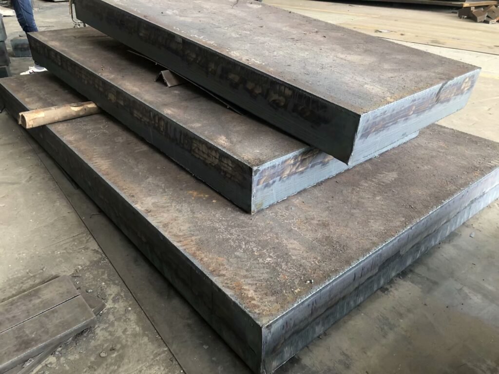
3. Step‑by‑Step Cutting Guide for Home / Workshop Use
3.1 Pre‑Cut Preparation
Thorough preparation guarantees cutting quality and safety; no steps can be skipped.
- Measurement and marking: Define dimensions with tape measure and square. Use a scriber or soapstone for cutting lines. For thick plates, punch indentations every 20‑30 mm along the cutting path with a center punch to avoid losing alignment when sparks obscure marks.
- Workpiece securing: Clamp steel plates firmly to workbenches using vices or G‑clamps. Leave open clearance beneath cutting lines. Support both ends of long plates to prevent bending or dropping after cutting.
- Work‑site clearance: Remove all combustible materials within a 5‑meter working radius and keep ABC‑type dry‑chemical fire extinguishers on‑hand. Ensure adequate ventilation to prevent fume accumulation. Do not cut directly on concrete floors; molten slag may cause concrete spalling and personal injury.
- Personal protective equipment: Wear impact‑resistant safety goggles or welding helmet, fire‑resistant leather gloves, long‑sleeve flame‑retardant workwear, and earplugs. For galvanized or painted plates, respirator masks are mandatory.
3.2 Operating Steps for Angle‑Grinder Cutting
Angle grinders are widely used for DIY jobs. Standard operating procedures greatly reduce hazards.
- Fit a dedicated metal‑cutting disc. Confirm the guard is properly installed. Inspect discs for cracks or chipping, then fasten flange nuts securely.
- Hold the tool firmly with both hands. Start the grinder and wait for full rotational speed before contacting the plate. Keep the cutting disc perpendicular to the steel surface.
- Advance steadily following marked lines. Let the tool’s own weight drive cutting; never force downwards or apply lateral pressure, which may shatter the disc.
- For long cuts, perform segmented operations and pause periodically for disc cooling to prevent thermal softening and failure.
- Upon completion, switch off power. Wait until the disc stops completely before setting down the tool. Do not grind workpieces using the side face of cutting discs.
3.3 Operating Steps for Entry‑Level Plasma Cutters
Entry‑level plasma cutters have low operational barriers. Follow these tips for good cutting results.
- Connect power supply and compressed‑air lines. Adjust air pressure to 0.5‑0.6 MPa and verify reliable workpiece grounding.
- Match current settings to plate thickness: roughly 30 A for 6‑mm steel; increase current as thickness rises.
- Strike the arc with the torch tilted 15°‑20° against the plate surface. Restore vertical orientation immediately after piercing through the material.
- Move the torch uniformly along cutting lines. Proper speed is indicated by even slag ejection from the plate underside. Excess speed fails full penetration; slow speed causes heavy dross buildup.
- Pause briefly at cut‑end positions to ensure complete penetration. Stop the arc before moving the torch away to avoid arc exposure and thermal burns.
3.4 Post‑Cut Handling
Cut completion does not finish the workflow; post‑processing directly affects end‑use performance.
- Deburr and remove dross: Clear oxide slag and dross on both cut faces with wire brushes and chisels. Use flap discs fitted on angle grinders to smooth edges.
- Bevel preparation: When welding is required, machine bevel angles with bevelers or angle grinders according to welding‑process specifications.
- Anti‑rust treatment: Freshly exposed cut surfaces corrode easily. Apply anti‑rust paint or anti‑rust oil promptly after machining.
- Part marking: For multiple‑part batches, mark part numbers, material grades and thicknesses right after cutting to avoid mixing‑up components.
Frequently Asked Questions
1、What maximum steel‑plate thickness can a household angle grinder cut?
A 125‑mm angle grinder delivers a theoretical maximum cutting depth of around 38 mm with standard discs. Considering power limits and safety risks, practical recommended thickness is ≤10 mm for balanced efficiency and safety. For material thicker than 10 mm, plasma cutting offers better quality and productivity.
2、Can a jigsaw cut steel plates without specialized tools?
Yes, but only for thin sheets ≤10 mm. Install bi‑metal jigsaw blades; 21‑23 TPI teeth are recommended. Jigsaws excel for curved and irregular profiles, but are unsuitable for long straight cuts or thick plates. Control feed rate to prevent blade breakage.
3、Is preheating mandatory for cutting thick steel plates?
Preheat to 100‑150 °C is recommended for oxy‑fuel cutting on plates above 20 mm, operations below 0 °C ambient temperature, or high‑carbon steel. This effectively prevents edge hardening and cracking. Preheating is generally unnecessary for plasma and laser cutting.
4、What is the most cost‑effective steel‑plate‑cutting solution?
For occasional small‑scale cutting, an angle grinder with metal‑cutting discs delivers the lowest tool‑and‑consumable entry cost. For frequent long‑term cutting on plates ≤25 mm, entry‑level plasma cutters provide superior overall cost‑performance with better efficiency and lower long‑term consumable expense than angle grinders.
5、How to achieve accurate straight cuts?
Clamp angle steel or aluminum extrusions beside cutting lines as guide rails, and run cutting tools against the guide to guarantee straightness. For thick plates, scribe lines and mark center‑punch indentations; alignment points remain visible even when sparks obscure marking lines.
Conclusion
Three core factors govern cutting‑process selection: plate thickness, precision requirements, and budget. Laser cutting or shearing are preferred for thin sheets; plasma or angle‑grinder cutting for medium‑thickness plates; oxy‑fuel flame cutting for heavy plates. Angle grinders offer broad applicability for home‑DIY scenarios, while entry‑level plasma cutters are advised for frequent continuous operations.
Regardless of cutting method, strictly follow safety operating specifications, wear complete personal‑protection gear, and implement fire‑prevention measures on‑site. Perform deburring and anti‑rust treatment after cutting to guarantee final machining quality and service life of components.




 English
  Spanish
  Afrikaans